Visual odometry
Visual odometry is part of the sensor dynamics component. It is used to estimate the camera’s motion from the motion of characteristic image points (so-called image features) in left camera images. Image features are computed from image corners, which are image regions with high intensity gradients. Image features are used to look for matches between subsequent images to find correspondences. Their 3D coordinates are computed by stereo matching (independent from the disparity image). The camera’s motion is computed from a set of corresponding 3D points between two images. To increase the robustness of visual odometry, correspondences are not only computed to the previous camera image but to a certain number of previous images, which are called keyframes. The best result is then chosen.
The visual-odometry frame rate is independent of the user setting in the stereo camera component. It is internally limited to 12 Hz but can be lower, depending on the number of features and keyframes. To ensure good pose-estimation quality, the frame rate should not drop significantly under 10 Hz.
The visual odometry component’s measurements are not directly accessible on the rc_visard. Instead, they are internally fused with measurements from the integrated inertial measurement unit to increase robustness and frame rate and reduce latency. The result of the sensor data fusion is provided in the form of different streams (see Stereo INS).
Parameters
The visual odometry software component is called rc_stereovisodo and it is represented by the
Dynamics tab in the Web GUI.
The user can change the visual odometry parameters there, or use the REST-API
(REST-API interface).
Parameter overview
This component offers the following run-time parameters.
| Name | Type | Min | Max | Default | Description |
|---|---|---|---|---|---|
disprange |
int32 | 32 | 512 | 256 | Disparity range in pixels |
ncorner |
int32 | 50 | 4000 | 500 | Number of corners |
nfeature |
int32 | 50 | 4000 | 300 | Number of features |
nkey |
int32 | 1 | 4 | 4 | Number of keyframes |
This component reports the following status values.
| Name | Description |
|---|---|
corner |
Number of detected corners. This value is shown as Corners below the image preview in the Web GUI. |
correspondences |
Number of correspondences. This value is shown as Correspondences below the image preview in the Web GUI. |
feature |
Number of features. This value is shown as Features below the image preview in the Web GUI. |
fps |
Frame rate of the visual odometry in Hertz. This value is shown below the image preview as Visual Odometry FPS (Hz) in the Web GUI. |
time_frame |
Processing time in seconds to compute corners and features for each frame |
time_vo |
Processing time in seconds to compute the motion |
Description of run-time parameters
Run-time parameters influence the number of features used to compute visual odometry. More features increase the visual odometry’s robustness at the expense of more run time, which can reduce the frame rate. Although the resulting state estimate will always have a high frequency due to fusion with IMU measurements, high visual-odometry frame rates are nevertheless desirable, since these measurements are much more accurate than IMU measurements alone. A visual-odometry rate of at least 10 Hz should thus be aimed for. The visual-odometry frame rate is provided as a status parameter and is shown below the camera image on the Web GUI’s Dynamics page.
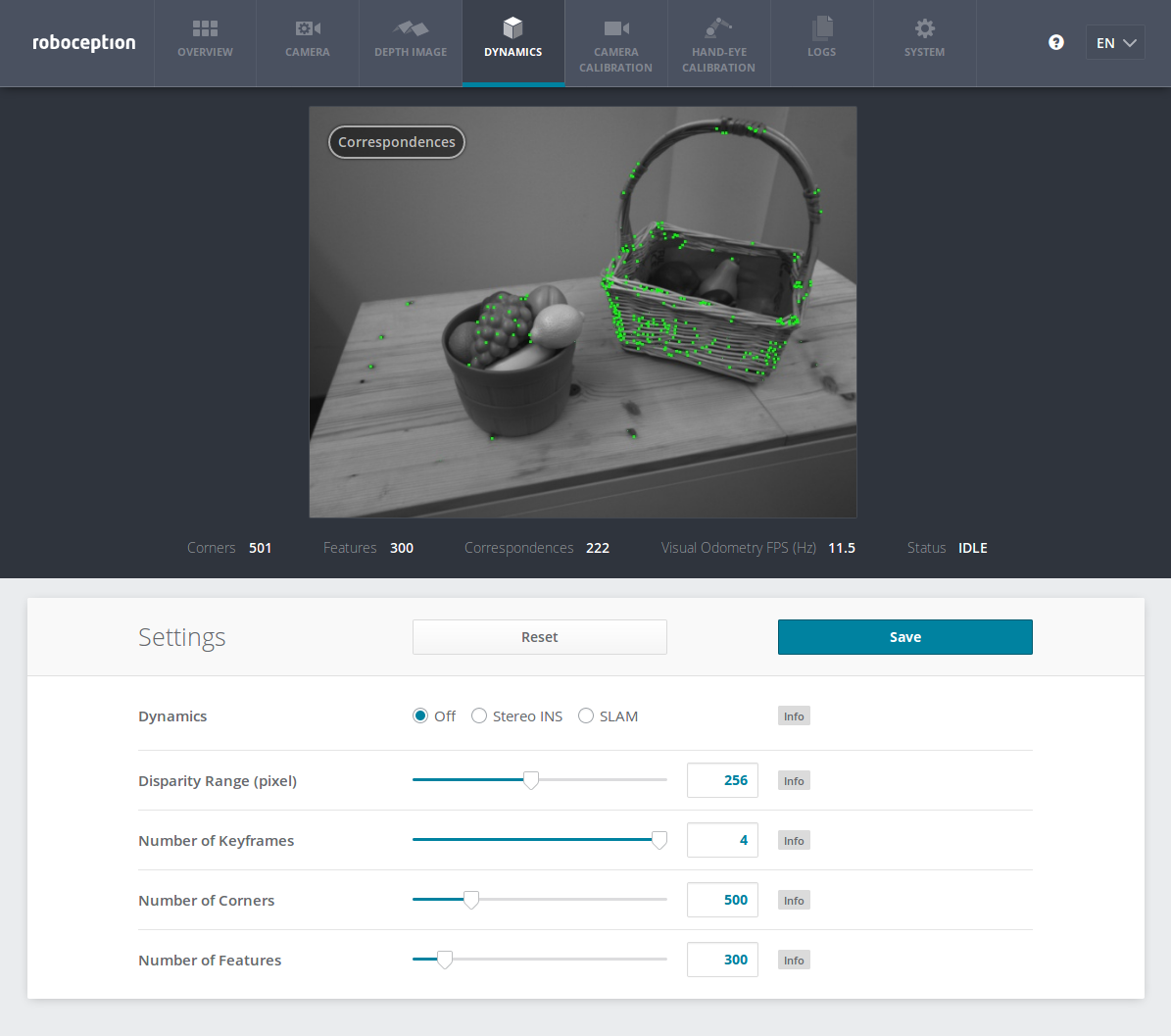
Fig. 25 The Web GUI’s Dynamics tab
The camera image shown on this page depicts image features as small green dots. The bold green dots are the features in the current image for which correspondences could be found in a previous keyframe. Green lines depict the motion of these features relative to the previous keyframe. This visualization should help to find a good set of parameters for visual odometry. The number of correspondences is reported as a status parameter and is shown below the camera image on the Web GUI’s Dynamics page. For robust visual-odometry measurements, the parameters should be adjusted so that the resulting number of correspondences in the target environment is around at least 50 when the sensor is moving. The correspondence count will be larger when the rc_visard is static, and the number will change when the rc_visard moves through the environment. Short failures of the visual odometry are tolerated due to the fusion with IMU measurements. Longer failures should be avoided because they lead to large pose uncertainties and can lead to errors in the state estimation.
Each run-time parameter is represented by a row on the Web GUI’s Dynamics tab. The name of the row is given in brackets behind the parameter name, and the parameters are listed in the order they appear in the Web GUI:
start(Dynamics)- This starts the sensor dynamics estimation components (see Services).
disprange(Disparity Range)- The disparity range gives the maximum disparity value for each image feature related to the resolution of the high-quality disparity image (640 x 480 pixels). The disparity range determines the minimum working distance of the visual odometry. When the disparity range is narrow, only more distant features are considered in the visual-odometry estimation. When choosing a broader disparity range, close features can also be used. Broader disparity ranges increase processing time, which can reduce the visual odometry’s frame rate.
nkey(Number of Keyframes)- More keyframes can increase the robustness and accuracy of the visual odometry, but they also increase processing time and can decrease the visual-odometry frame rate.
ncorner(Number of Corners)- This value gives the approximate number of corners that will be detected in the left image. Larger numbers make visual odometry more robust and accurate but can lead to lower frame rates of the visual odometry.
nfeature(Number of Features)- This value is the maximum number of features that will be derived from the corners. It is useful to detect more corners and select the best subset as features. Larger numbers make visual odometry more robust and accurate but can lead to lower visual-odometry frame rates. Fewer features might be computed, depending on the scene and movement. The actual number of features is reported below the camera image on the Web GUI’s Dynamics page.
Note
Increasing the number of keyframes, corners, or features will also increase robustness but will require more computation time and may reduce the frame rate, depending on other components active on the rc_visard. The visual-odometry frame rate should be at least 10 Hz.
Services
The visual odometry component offers the following services for persisting and restoring parameter settings. The names of the corresponding Web GUI buttons are added in brackets:
save_parameters(Save)With this service call, the current parameter settings of the visual odometry component are persisted to the rc_visard. That is, these values are applied even after reboot.
This service requires no arguments.
This service returns no response.
reset_defaults(Reset)Restores and applies the default values for this component’s parameters (“factory reset”).
Warning
The user must be aware that calling this service causes irrecoverable loss of the visual odometry component’s current parameter settings.
This service requires no arguments.
This service returns no response.
This component offers no start or stop services itself, because the dynamics component starts and stops it.