Installation
Warning
The instructions on Safety related to the rc_visard must be read and understood prior to installation.
Installation and configuration
The rc_visard offers a Gigabit Ethernet interface for connecting the device to a computer network. All communications to and from the device are performed via this interface. The rc_visard has an on-board computing resource that requires booting time after powering up the device.
Power up
Note
Always fully connect and tighten the M12 power connector on the rc_visard before turning on the power supply.
After connecting the rc_visard to the power, the LED on the front of the device should immediately illuminate. During the device’s boot process, the LED will change color and will eventually turn green. This signals that all processes are up and running.
If the network is not plugged in or the network is not properly configured, then the LED will flash red every 5 seconds. In this case, the device’s network configuration should be verified. See LED colors for more information on the LED color codes.
Network configuration
The rc_visard requires an Internet Protocol (IP) address for communication with other network devices. The IP address must be unique in the local network, and can be set automatically or manually.
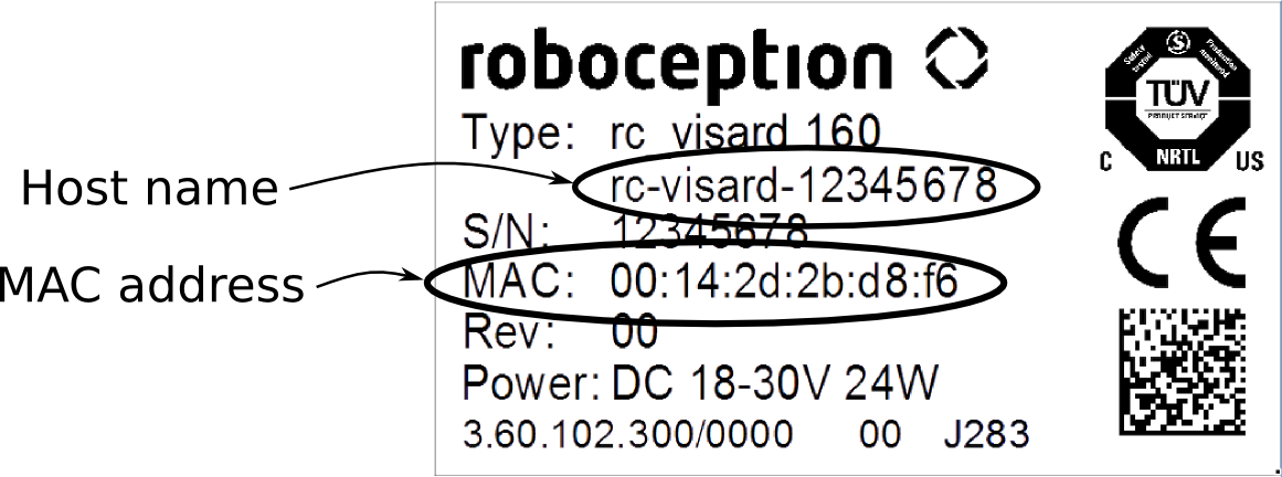
Fig. 12 Label on the rc_visard
Automatic configuration (factory default)
The Dynamic Host Configuration Protocol (DHCP) is preferred for setting an IP address. If DHCP is active on the rc_visard, which is the factory default, then the device tries to contact a DHCP server at startup and every time the network cable is plugged in. If a DHCP server is available on the network, then the IP address is automatically configured.
In some networks, the DHCP server is configured so that it only accepts known
devices. In this case, the Media Access Control address (MAC address), which is printed on
the sensor label, needs to be configured in the DHCP server. At the same time, the sensor’s host
name can also be set in the Domain Name Server (DNS). The host name is
defined as rc-visard-<serial number>, which is also printed on the sensor. Both MAC
address and host name should be sent to the network administrator for configuration.
If the rc_visard cannot contact a DHCP server for about 15 seconds after startup or after plugging in the network cable, it will try to assign itself a unique IP address. This process is called Link Local. This option is especially useful for connecting the rc_visard directly to a computer. The computer must be configured for Link Local as well. Link Local might already be configured as a standard fallback option, as it is under Windows 10. Other operating systems such as Linux require Link Local to be explicitly configured in their network managers.
Manual configuration
Specifying a persistent IP address manually might be useful in come cases. This is done via the sensor’s standard GigE Vision® 2.0 interface, and requires a configuration tool to be installed on the host computer. We recommend using the IpConfigTool that is part of the Baumer GAPI SDK. The SDK can be downloaded free of charge for Windows and Linux from http://www.baumer.com.
After the configuration tool starts, it scans for all available GigE Vision® sensors on the network. All rc_visard devices can be uniquely identified by their serial number and MAC address, which are both printed on the device. If the device cannot be found, it can also be connected directly to the computer for configuration (see Automatic configuration (factory default)).
Warning
The IP address must be unique and within the local network’s range of valid addresses. Furthermore, the subnet mask must match the local network; otherwise, the rc_visard may become inaccessible. This can be avoided by using automatic configuration as explained in Automatic configuration (factory default).
Discovery of rc_visard devices
Devices that are powered up and connected to the local network or directly to a
computer (see Network configuration)
can be found using the standard GigE Vision® discovery mechanism.
Roboception offers the open-source tool rcdiscover-gui, which can be downloaded free of charge from
http://www.roboception.com/download for Windows and Linux.
The tool’s Windows version consists of a single executable for Windows 7 and Windows 10, which can be executed without installation.
For Linux an installation package is available for Ubuntu 14.04 and 16.04.
At startup, all available rc_visard devices are
listed with their names, serial numbers, current IP addresses, and unique MAC addresses. The
discovery tool finds all devices reachable by global broadcasts. Misconfigured devices
that are located in different subnets than the computer may also be listed. An icon in the
discovery tool indicates whether devices are actually reachable via a
web browser.
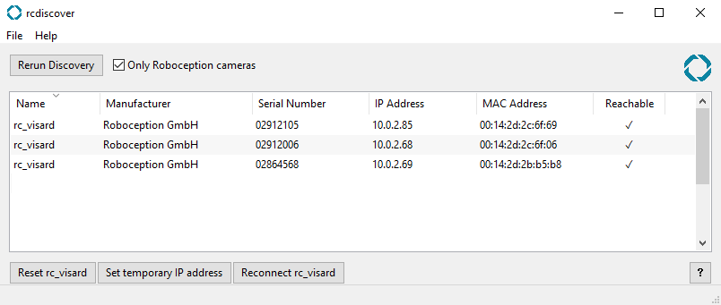
Fig. 13 rcdiscover-gui tool for finding connected rc_visard devices
After successful discovery, a double click on the device row opens the Web GUI of the device in the operating system’s default web browser. Mozilla Firefox is recommended as web browser.
Resetting configuration
A misconfigured device can be reset by using the Reset rc_visard button in the discovery tool. The reset mechanism is only available for two minutes after device startup. Thus, the rc_visard may require rebooting before being able to reset the device.
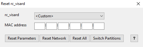
Fig. 14 Reset dialog of the rcdiscover-gui tool
If the discovery tool still successfully detects the the misconfigured rc_visard, then the latter can be selected from the rc-visard drop-down menu. Otherwise, the rc_visard’s MAC address, which is printed on the device label, can be entered manually into the designated fields.
One of four options can be chosen after entering the MAC address:
- Reset Parameters: Reset all rc_visard parameters, such as frame rate, that are configurable via Web GUI.
- Reset Network: Reset network settings and user-defined name.
- Reset All: Reset the rc_visard parameters as well as network settings and user-defined name.
- Switch Partitions: Allows a rollback to be performed as described in Restoring the previous firmware version.
A white status LED followed by a device reboot indicates a successful reset. If no reaction is noticeable, the two minutes time slot may have elapsed, requiring another reboot.
Note
The reset mechanism is only available for the first two minutes after startup.
Web GUI
The rc_visard’s Web GUI can be used to test, calibrate, and configure on-board processing.
It can be accessed from any web browser, such as Firefox, Google Chrome, or Microsoft Edge, via
the sensor’s IP address. The easiest way to access the Web GUI is to simply double click on the
desired device using the rcdiscover-gui tool as explained in Discovery of rc_visard devices.
Alternatively, some network environments automatically configure the unique host name of
the rc_visard in their Domain Name Server (DNS). In this case, the Web GUI can also be
accessed directly using the URL http://rc-visard-<serial-number> by
replacing <serial-number> with the serial number printed on the device label.
For Linux and Mac operating systems, this even works without DNS via the multicast
Domain Name System (mDNS), which is automatically used if .local is appended to the
host name. Thus, the URL simply becomes http://rc-visard-<serial-number>.local.
The Web GUI’s overview page gives the most important information about on-board processing.
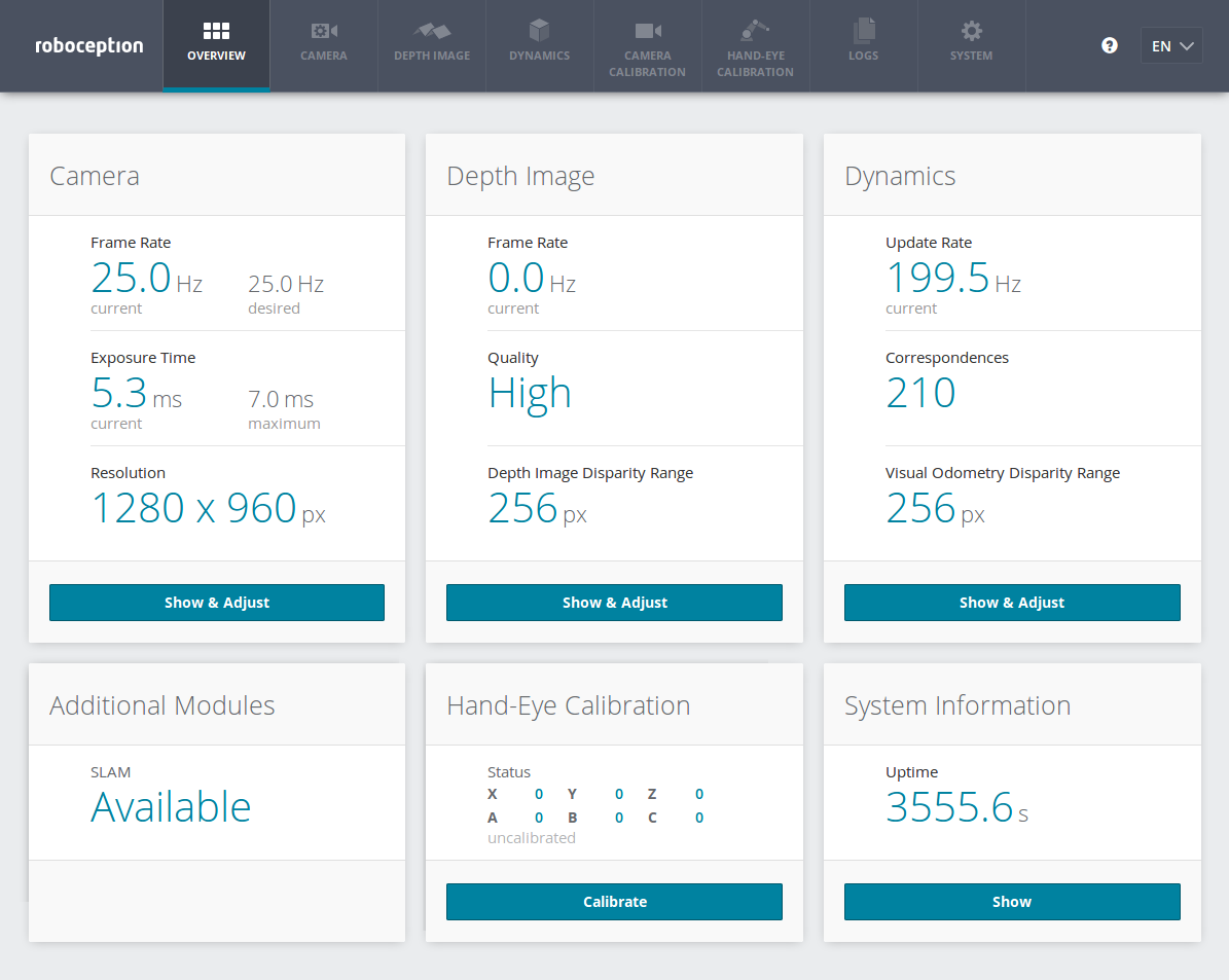
Fig. 15 Overview page of the rc_visard’s Web GUI
The page’s top row permits access to the individual rc_visard modules.
- The Camera module shows a live stream of the device’s left and right rectified images. The frame rate can be reduced to save bandwidth when streaming to a GigE Vision® client. Furthermore, exposure can be set manually or automatically. See Parameters for more information.
- The Depth Image module shows a live stream of the left rectified, depth, and confidence images. The page contains various settings for depth-image computation and filtering. See Parameters for more information.
- The Dynamics module shows the location and movement of image features that are used to compute the rc_visard’s egomotion. Settings include the number of corners and features that should be used. See Parameters for more information.
- The Camera Calibration module permits the camera to be checked for proper calibration. In rare cases when the camera is no longer sufficiently calibrated, calibration also can be performed using this module. See Camera calibration for more information.
- The Hand-Eye-Calibration module allows the computation of the static transformation between the rc_visard and a coordinate system known in the robot system. This can be the flange coordinate system of a robotic arm if the rc_visard is attached to the flange. Alternatively, the rc_visard may be mounted statically in the robot environment and calibrated to any other static frame known in the robot system. See Hand-eye calibration for more information.
- The Logs module permits access to the log files on the rc_visard. The log files are typically checked if errors are suspected.
- The System module permits the firmware or the license file to be updated and provides some general information about the device.
Changed parameters are not persistent and will be lost when restarting the rc_visard unless they are saved by pressing the Save button before leaving the corresponding page.
Further information on all parameters in the Web GUI can be obtained by pressing the Info button next to each parameter.