Stereo matching
The stereo matching component uses the rectified stereo-image pair and computes disparity, error, and confidence images.
Computing disparity images
After rectification, the left and right images have the nice property that an object point is projected onto the same pixel row in both images. That point’s pixel column in the right image is always lower than or equal to the same point’s pixel column in the left image. The term disparity signifies the difference between the pixel columns in the right and left images and expresses the depth or distance of the object point from the rc_visard. The disparity image stores the disparity values of all pixels in the left camera image.
The larger the disparity, the closer the object point. A disparity of 0 means that the projections of the object point are in the same image column and the object point is at infinite distance. Often, there are pixels for which disparity cannot be determined. This is the case for occlusions that appear on the left sides of objects, because these areas are not seen from the right camera. Furthermore, disparity cannot be determined for textureless areas. Pixels for which the disparity cannot be determined are marked as invalid with the special disparity value of 0. To distinguish between invalid disparity measurements and disparity measurements of 0 for objects that are infinitely far away, the disparity value for the latter is set to the smallest possible disparity value above 0.
To compute disparity values, the stereo matching algorithm has to find corresponding object points in the left and right camera images. These are points that represent the same object point in the scene. For stereo matching, the rc_visard uses SGM (Semi-Global Matching), which offers brief run times and a great accuracy, especially at object borders, fine structures, and in weakly textured areas.
A key requirement for any stereo matching method is the presence of texture in the image, i.e., image-intensity changes due to patterns or surface structure within the scene. In completely untextured regions such as a flat white wall without any structure, disparity values can either not be computed or the results are erroneous or have low confidence (see Confidence and error images). The texture in the scene should not be an artificial, repetitive pattern, since those structures may lead to ambiguities and hence to wrong disparity measurements.
If the rc_visard has to work in untextured environments, then a static artificial texture can be projected onto the scene using an external pattern projector. This pattern should be random-like and not contain repetitive structures.
Computing depth images and point clouds
The following equations show how to compute an object point’s actual 3D coordinates \(P_x, P_y, P_z\) in the sensor coordinate frame from the disparity image’s pixel coordinates \(p_{x}, p_{y}\) and the disparity value \(d\) in pixels:
where \(f\) is the focal length after rectification in pixels and \(t\) is the stereo baseline in meters, which was determined during calibration. These values are also transferred over the GenICam interface (see Custom GenICam features of the rc_visard).
Note
The rc_visard reports a focal length factor via its various interfaces. It relates to the image width for supporting different image resolutions. The focal length \(f\) in pixels can be easily obtained by multiplying the focal length factor by the image width in pixels.
Please note that equations (1) assume that the coordinate frame is centered in the middle of the image. The following figure shows the definition of the image coordinate frame.
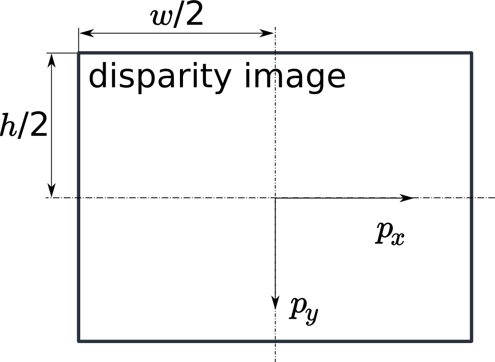
Fig. 21 The image coordinate frame’s origin is defined to be at the image’s center – \(w\) is the image width and \(h\) is the image height.
The same equations, but with the corresponding GenICam parameters are given in Image stream conversions.
The set of all object points computed from the disparity image gives the point cloud, which can be used for 3D modeling applications. The disparity image is converted into a depth image by replacing the disparity value in each pixel with the value of \(P_z\).
Note
Roboception provides software and examples for receiving disparity images from the rc_visard via GigE Vision and computing depth images and point clouds. See http://www.roboception.com/download.
Confidence and error images
For each disparity image, the rc_visard provides an error image and a confidence image, which give uncertainty measures for each disparity value. These images have the same resolution and the same frame rate as the disparity image. The error image contains the disparity error \(d_{eps}\) in pixels corresponding to the disparity value at the same image coordinates in the disparity image. The confidence image contains the corresponding confidence value \(c\) between 0 and 1. The confidence is defined as the probability of the true disparity value being within the interval of three times the error around the measured disparity \(d\), i.e., \([d-3d_{eps}, d+3d_{eps}]\). Thus, the disparity image with error and confidence values can be used in applications requiring probabilistic inference. The confidence and error values corresponding to an invalid disparity measurement will be 0.
The disparity error \(d_{eps}\) (in pixels) can be converted to a depth error \(z_{eps}\) (in meters) using the focal length \(f\) (in pixels), the baseline \(t\) (in meters), and the disparity value \(d\) (in pixels) of the same pixel in the disparity image:
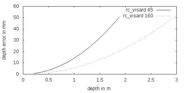
Combining equations (1) and (2) allows the depth error to be related to the depth:
With the focal length and baselines of both rc_visard models and the typical disparity error \(d_{eps}\) of 0.5 pixels, the depth error can be visualized as shown below.
The rc_visard provides time-stamped disparity, error, and confidence images over the GenICam interface (see Chunk data). Live streams of the images are provided with reduced quality in the Web GUI.
Parameters
The stereo matching component is called rc_stereomatching in the REST-API and it is represented by the
Depth Image tab in the Web GUI.
The user can change the stereo matching parameters there, or use the REST-API
(REST-API interface) or GigE Vision
(GigE Vision 2.0/GenICam image interface).
Parameter overview
This component offers the following run-time parameters.
| Name | Type | Min | Max | Default | Description |
|---|---|---|---|---|---|
disprange |
int32 | 32 | 512 | 256 | Disparity range in pixels |
fill |
int32 | 0 | 4 | 3 | Disparity tolerance for hole filling in pixels |
maxdepth |
float64 | 0.1 | 100.0 | 100.0 | Maximum depth in meters |
maxdeptherr |
float64 | 0.01 | 100.0 | 100.0 | Maximum depth error in meters |
median |
int32 | 1 | 5 | 1 | Window size for median filtering in pixels |
minconf |
float64 | 0.5 | 1.0 | 0.5 | Minimum confidence |
mindepth |
float64 | 0.1 | 100.0 | 0.1 | Minimum depth in meters |
quality |
string | - | - | H | S(taticHigh), H(igh), M(edium), or L(ow). |
seg |
int32 | 0 | 4000 | 200 | Minimum size of valid disparity segments in pixels |
This component reports the following status values.
| Name | Description |
|---|---|
fps |
Actual frame rate of the disparity, error, and confidence images. This value is shown in the Web GUI below the image preview as FPS (Hz). |
time_matching |
Time in seconds for performing stereo matching using SGM on the GPU |
time_postprocessing |
Time in seconds for postprocessing the matching result on the CPU |
Since SGM stereo matching and post processing run in parallel, the overall processing time for
this component is the maximum of time_matching and time_postprocessing. This time is
shown in the Web GUI below the image preview as Processing Time (s).
Description of run-time parameters
Each run-time parameter is represented by a row on the Web GUI’s Depth Image tab. The name in the Web GUI is given in brackets behind the parameter name and the parameters are listed in the order they appear in the Web GUI:
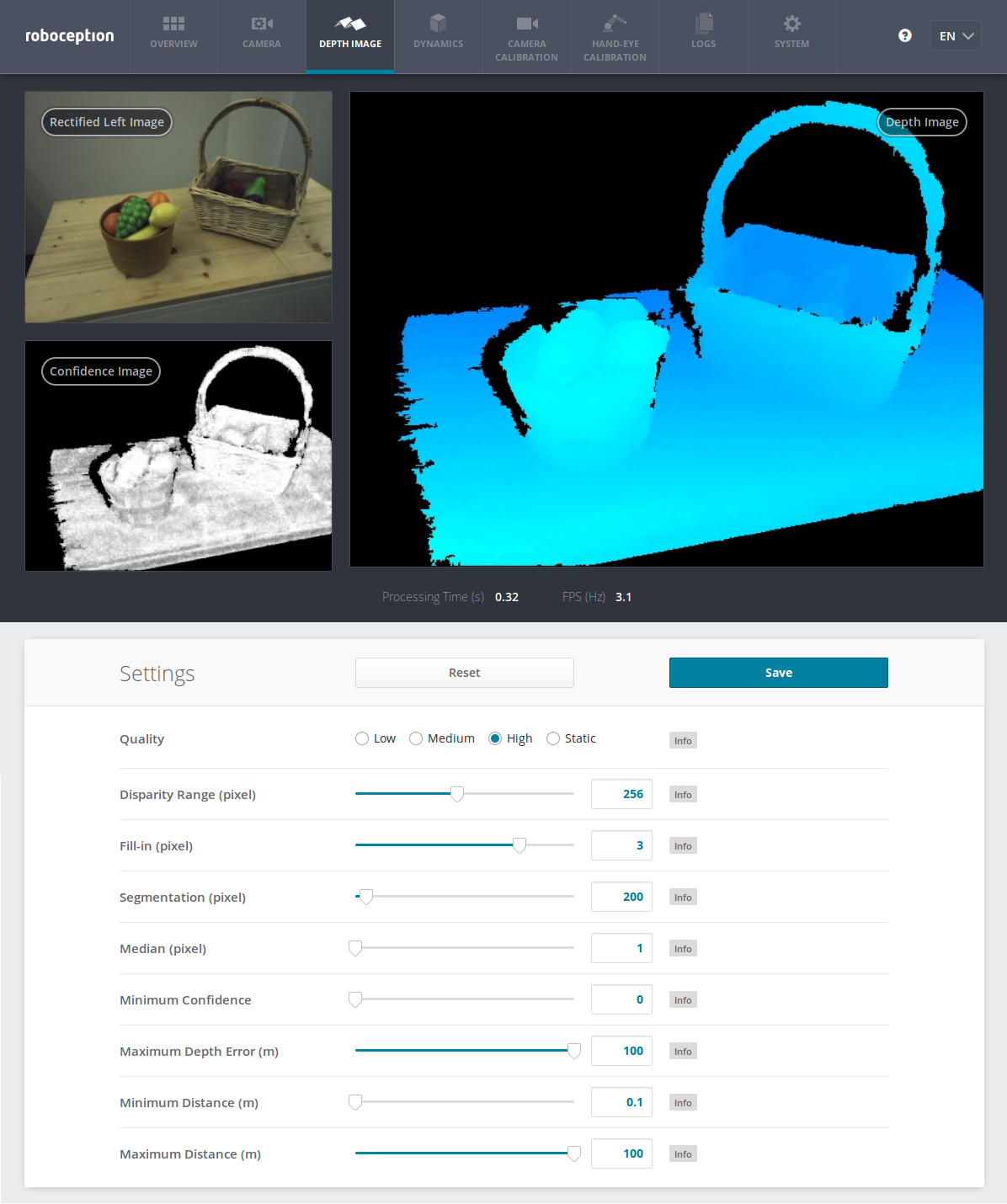
Fig. 22 The Web GUI’s Depth Image tab
quality(Quality)- Disparity images can be computed in three different resolutions: high (640 x 480), medium (320 x 240) and low (214 x 160). The lower the resolution, the higher the frame rate of the disparity image. A 25 Hz frame rate can be achieved only at the lowest resolution. Additionally, static can be chosen, which means high-resolution processing, limited to a maximal frame rate of 3 Hz and accumulation of all intermediate input images. The accumulation reduces noise, but is only suitable if the scene does not change. Please note that the frame rate of the disparity, confidence, and error images will always be less than or equal to the camera frame rate.
disprange(Disparity Range)- The disparity range always start at 0 and goes up to the maximum disparity value a pixel in the disparity image can have. Increasing the disparity range results in a smaller minimum distance that can be measured, because larger disparity values mean smaller distances. The disparity range is given in pixels and can be set to a value between 32 pixels and 512 pixels. Since a larger disparity range also means a larger search area for the matching pixel in the right rectified image, the processing time increases with a larger disparity range and the frame rate decreases. The disparity range’s value is related to the high-resolution disparity image with 640 x 480 pixels and does not have to be scaled when a lower resolution is chosen. Thus, the chosen disparity range gives the same minimum distance for every image-quality option.
fill(Fill-in)- This option is used to fill holes in the disparity image by interpolating a plane. Only holes smaller than the segmentation size (see below) are selected for interpolation. The fill-in value is the maximum allowed disparity deviation of any of the hole’s border pixels from the interpolation plane. Only if all of its border pixels deviate less than the fill-in value from the plane, a hole will be filled. Larger fill-in values decrease the number of holes, but the interpolated values can have larger errors. The confidence for the interpolated pixels is set to a low value of 0.5. Their error is set to the mean deviation of the hole border pixels from the interpolation plane. A value of 0 effectively switches hole filling off.
seg(Segmentation)- The segmentation parameter is used to set the minimum number of pixels that a connected disparity region in the disparity image must fill. Isolated regions that are smaller are set to invalid in the disparity image. This is useful for removing erroneous disparities. However, larger values may also remove real objects.
median(Median)- This value gives the window side length in pixels for the median filter, which smoothes the disparity image. Larger values lead to oversmoothing and cost more processing time. A window size of 1 effectively turns this filter off.
minconf(Minimum Confidence)- The minimum confidence can be set to filter potentially false disparity measurements. All pixels with less confidence than the chosen value are set to invalid in the disparity image.
maxdeptherr(Maximum Depth Error)- The maximum depth error is used to filter measurements that are too inaccurate. All pixels with a larger depth error than the chosen value are set to invalid in the disparity image. The maximum depth error is given in meters. The depth error generally grows quadratically with an object’s distance from the sensor (see Confidence and error images).
mindepth(Minimum Distance)- The minimum distance is the smallest distance from the sensor at which measurements should be possible. Larger values implicitly reduce the disparity range, which also reduces the computation time. The minimum distance is given in meters.
maxdepth(Maximum Distance)- The maximum distance is the largest distance from the sensor at which measurements should be possible. Pixels with larger distance values are set to invalid in the disparity image. Setting this value to its maximum permits values up to infinity. The maximum distance is given in meters.
The same parameters are also available over the GenICam interface with slightly different names and partly with different data types (see GigE Vision 2.0/GenICam image interface).
Services
The stereo matching component offers the following services for persisting and restoring parameter settings.
save_parameters(Save)With this service call, the stereo matching component’s current parameter settings are persisted to the rc_visard. That is, these values are applied even after reboot.
This service requires no arguments.
This service returns no response.
reset_defaults(Reset)Restores and applies the default values for this component’s parameters (“factory reset”).
Warning
The user must be aware that calling this service causes the current parameter settings for the stereo matching component to be irrecoverably lost.
This service requires no arguments.
This service returns no response.