Hardware specification
Note
The following hardware specifications are provided here as a general reference; differences with the product might exist.
Scope of delivery
Standard delivery for an rc_visard includes the rc_visard sensor and a quickstart guide only. The full manual is available in digital form and is always installed on the sensor, accessible through the Web GUI, and available at http://www.roboception.com/documentation.
Note
The following items are not included in the delivery unless otherwise specified:
- Couplings, adapters, mounts
- Power supply unit, cabling, and fuses
- Network cabling
Please refer to Accessories for suggested third-party cable vendors.
A connectivity kit can be purchased for the rc_visard. It contains an M12 to RJ45 network cable, 24 V power supply, and a DC plug to M12 power adapter. Please refer to Accessories for details.
Note
The connectivity kit is intended only for initial setup, not for permanent installation in industrial environment.
The following picture shows the important parts of the rc_visard which are referenced later in the documentation.
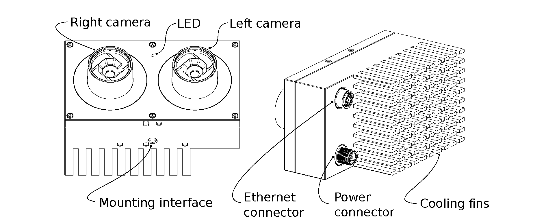
Fig. 2 Parts description
Technical specification
The common technical specifications for both rc_visard variants are given in Table 1.
| rc_visard 65 / rc_visard 160 | |
|---|---|
| Image resolution | 1280 x 960 pixel, color or monochrome |
| Field of view | Horizontal: 61°, Vertical: 48° |
| IR Cutoff | 650 nm |
| Depth image | 640 x 480 pixel (high) @ 3 Hz
320 x 240 pixel (medium) @ 15 Hz
214 x 160 pixel (low) @ 25 Hz
|
| Egomotion | 200 Hz, low latency |
| Computing unit | Nvidia Tegra K1 |
| Power supply | 18 V to 30 V |
| Cooling | Passive |
The rc_visard 65 and rc_visard 160 differ in their baselines, which affects depth range and resolution as well as the sensors’ size and weight.
| rc_visard 65 | rc_visard 160 | |
|---|---|---|
| Baseline | 65 mm | 160 mm |
| Depth range | 0.2 m to infinity | 0.5 m to infinity |
| Depth resolution | 0.5 mm @ 0.2 m
15 mm @ 1.0 m
|
1.5 mm @ 0.5 m
6 mm @ 1.0 m
23 mm @ 2.0 m
50 mm @ 3.0 m
|
| Size (W x H x L) | 135 mm x 75 mm x 96 mm | 230 mm x 75 mm x 84 mm |
| Mass | 0.68 kg | 0.84 kg |
The rc_visard can be equipped with on-board software modules such as SLAM for additional features. These software modules can be ordered and require a license update.

Fig. 3 Overall dimensions of the rc_visard 65

Fig. 4 Overall dimensions of the rc_visard 160
CAD models of the rc_visard can be downloaded from http://www.roboception.com/download. The CAD models are provided as-is, with no guarantee of correctness. When a material property of aluminium is assigned (density of \(2.76\mathrm{g\over{cm}^3}\)), the mass properties of the CAD model are within 5% of the product with respect to weight and center of mass, and within 10% with respect to moment of inertia.
Environmental and operating conditions
The rc_visard is designed for industrial applications. Always respect the storage, transport, and operating environmental conditions outlined in Table 3.
| rc_visard 65 / rc_visard 160 | |
|---|---|
| Storage/Transport temperature | -25 °C to 70 °C |
| Operating temperature | 0 °C to 50 °C |
| Relative humidity (non condensing) | 20 % to 80 % |
| Vibration | 5 g |
| Shock | 50 g |
| Protection class | IP54 |
| Others |
|
The rc_visard is designed for an operating (surrounding environment) temperature of 0 °C to 50 °C and relies on convective (passive) cooling. Unobstructed airflow, especially around the cooling fins, needs to be ensured during use. The rc_visard should only be mounted using the provided mechanical mounting interface, and each part of the housing must remain uncovered. A free space of at least 10 cm extending in all directions from the housing, and sufficient air exchange with the environment is required to ensure adequate cooling. Cooling fins must be free of dirt and other contamination.
The housing temperature depends on the processing load, sensor orientation, and surrounding environmental temperatures. When the sensor’s exposed housing surfaces exceed 60°C, the LED at the front will turn from green to red.
Warning
For hand-guided applications, a heat-insulated handle should be attached to the sensor to reduce the risk of burn injuries due to skin exposure to surface temperatures exceeding 60°C.
Power-supply specifications
The rc_visard needs to be supplied by a DC voltage source. The rc_visard’s standard package doesn’t include a DC power supply. The power supply contained in the connectivity kit may be used for initial setup. For permanent installation, it is the customer’s responsibility to provide suitable DC power. The sensor is qualified as industrial equipment Class A under EN55011. As such, each rc_visard must be connected to a separate power supply. Connection to domestic grid power is only allowed through a power supply certified as EN55011 Class B.
| Min | Nominal | Max | |
|---|---|---|---|
| Supply voltage | 18.0 V | 24 V | 30.0 V |
| Max power consumption | 25 W | ||
| Overcurrent protection | Supply must be fuse-protected to a maximum of 2 A | ||
| EMC compliance | Industrial equipment under EN55011 Class A | ||
Warning
Exceeding maximum power rating values may lead to damage of the rc_visard, power supply, and connected equipment.
Warning
A separate power supply must power each rc_visard.
Warning
Connection to domestic grid power is allowed through a power supply certified as EN55011 Class B only.
Wiring
Cables are not provided with the rc_visard standard package. It is the customer’s responsibility to obtain the proper cabling. Accessories provides an overview of suggested components.
Warning
Proper cable management is mandatory. Cabling must always be secured to the rc_visard mount with a strain-relief clamp so that no forces due to cable movements are exerted on the rc_visard’s M12 connectors. Enough slack needs to be provided to allow for full range of movement of the rc_visard without straining the cable. The cable’s minimum bend radius needs to be observed.
The rc_visard provides an industrial 8-pin A-coded M12 socket connector for Ethernet connectivity and an 8-pin A-coded M12 plug connector for power and GPIO connectivity. Both connectors are located at the back. Their locations (distance from centerlines) are identical for the rc_visard 65 and rc_visard 160. The location of both connectors on the rc_visard 65 is shown as an example in Fig. 5.
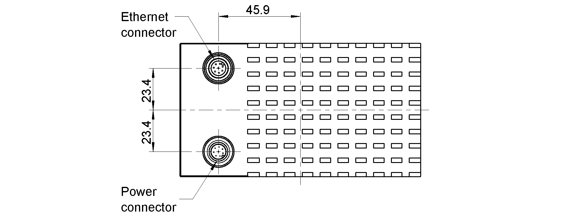
Fig. 5 Locations of the electrical connections for the rc_visard 65, with Ethernet on top and power on the bottom
Connectors are rotated so that standard 90° angled connectors will exit horizontally, away from the camera (away from the cooling fins).
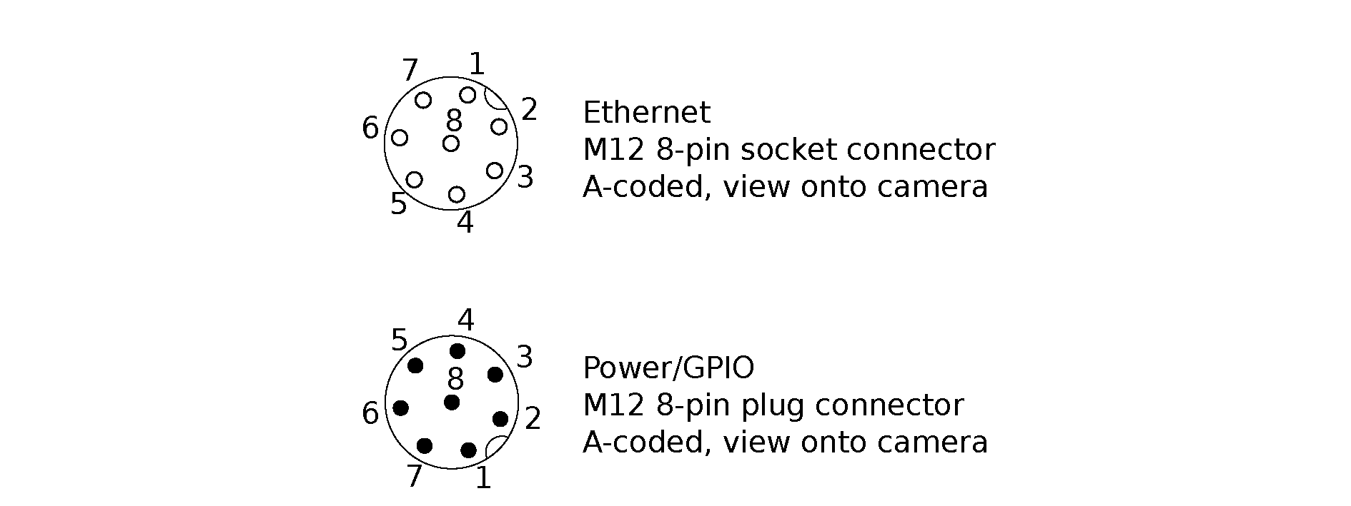
Fig. 6 Pin positions for power and Ethernet connector
Pin assignments for the Ethernet connector are given in Fig. 7.

Fig. 7 Pin assignments for M12 to Ethernet cabling
Pin assignments for the power connector are given in Table 5.
| Pin | Assignment |
|---|---|
| 1 | GPIO In 2 |
| 2 | Power |
| 3 | GPIO In 1 |
| 4 | GPIO Gnd |
| 5 | GPIO Vcc |
| 6 | GPIO Out 1 (image exposure) |
| 7 | Gnd |
| 8 | GPIO Out 2 |
GPIOs are decoupled by photocoupler. GPIO Out 1 by default provides an exposure sync signal with a logic high level for the duration of the image exposure. All GPIOs can be controlled via the optional IOControl component (IO and Projector Control). Pins of unsused GPIOs should be left floating.
Warning
It is especially important that during the boot phase GPIO In 1 is left floating or remains low. The rc_visard will not boot if the pin is high during boot time.
GPIO circuitry and specifications are shown in Fig. 8. The maximum rated voltage for GPIO In and GPIO Vcc is 30 V.
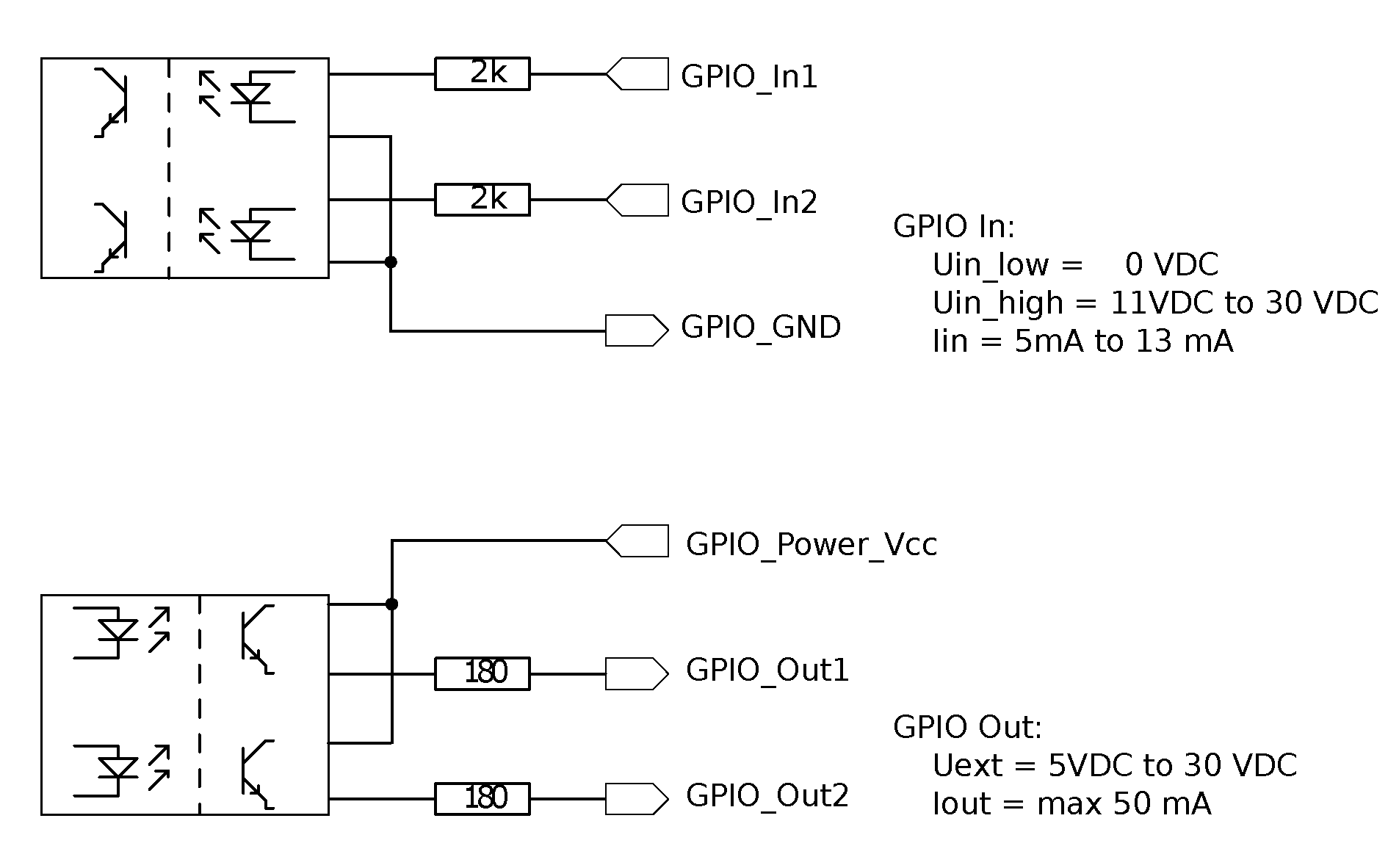
Fig. 8 GPIO circuitry and specifications – do not connect signals higher than 30 V
Warning
Do not connect signals with voltages higher than 30 V to the rc_visard.
Mechanical interface
The rc_visard 65 and rc_visard 160 offer identical mounting-point setups at the bottom.
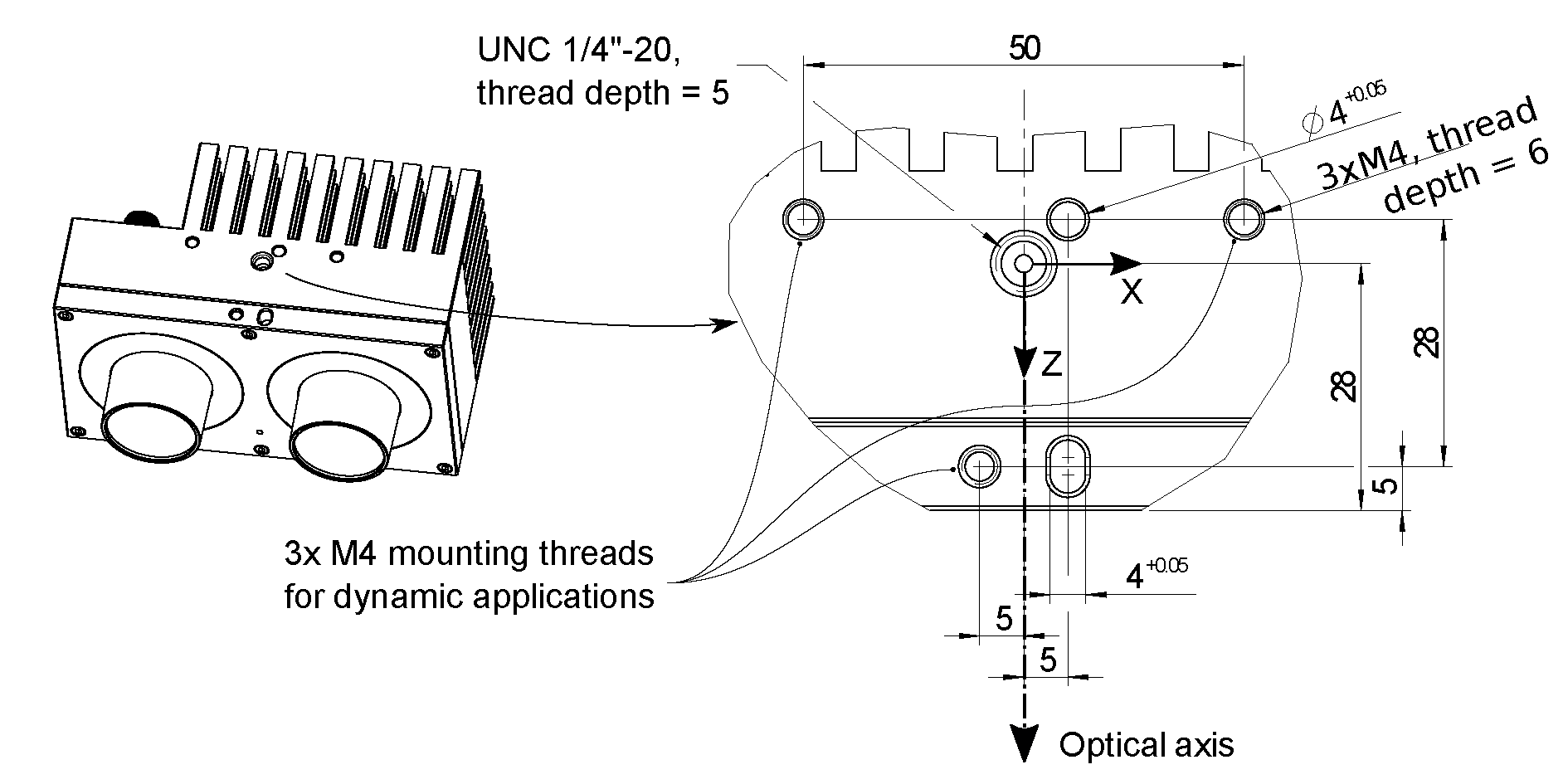
Fig. 9 Mounting-point for connecting the rc_visard to robots or other mountings
For troubleshooting and static applications, the sensor may be mounted using the standardized tripod thread (UNC 1/4”-20) indicated at the coordinate-frame origin. For dynamic applications such as mounting on a robotic arm, the sensor must be mounted with three M4 (metric standard) 8.8 machine screws tightened to 2.5 Nm and secured with a medium-strength threadlocking adhesive such as Loctite 243. Maximum thread depth is 6 mm. The two 4 mm diameter holes may be used for positioning pins (ISO 2338 4 m6) to ensure precise repositioning of the sensor.
Warning
For dynamic applications, the rc_visard must be mounted with three M4 8.8 machine screws tightened to 2.5 Nm torque and secured with threadlocking adhesive. Do not use high-strength bolts. The engaged thread depth must be at least 5 mm.
Coordinate frames
The rc_visard’s coordinate-frame origin is defined as the exit pupil of the left camera lens. This frame is called sensor coordinate frame or camera coordinate frame. An approximate location for the rc_visard 65 is shown in the next image.
The mounting-point frame for both rc_visard devices is defined to be at the bottom, centered in the tripod thread, with orientation identical to that of the sensor’s coordinate frame. Fig. 10 shows approximate offsets.

Fig. 10 Approximate location of sensor/camera coordinate frame (inside left lens) and mounting-point frame (at tripod thread) for the rc_visard 65
Approximate locations of sensor/camera coordinate frame and mounting-point frame for the rc_visard 160 are shown in Fig. 11.

Fig. 11 Approximate locations of sensor/camera coordinate frame (inside left lens) and mounting-point frame (at tripod thread) for the rc_visard 160
Note
The correct offset between the sensor/camera frame and a robot coordinate frame can be calibrated through the hand-eye-calibration procedure