Camera calibration
The camera calibration module is a base module which is available on every rc_visard.
To use the camera as measuring instrument, camera parameters such as focal length, lens distortion, and the relationship of the cameras to each other must be exactly known. The parameters are determined by calibration and used for image rectification (see Rectification), which is the basis for all other image processing modules.
The rc_visard is calibrated at production time. Nevertheless, checking calibration and recalibration might be necessary if the rc_visard was exposed to strong mechanical impact.
The camera calibration module is responsible for checking calibration and calibrating.
Self-calibration
The camera calibration module automatically runs in self-calibration mode at a low frequency in the background. In this mode, the rc_visard observes the alignment of image rows of both rectified images. A mechanical impact, such as one caused by dropping the rc_visard, might result in a misalignment. If a significant misalignment is detected, then it is automatically corrected. After each reboot and after each correction, the current self-calibration offset is reported in the camera module’s log file (see Downloading log files) as:
“rc_stereocalib: Current self-calibration offset is 0.00, update counter is 0”
The update counter is incremented after each automatic correction. It is reset to 0 after manual recalibration of the rc_visard.
Under normal conditions, such as the absence of mechanical impact on the rc_visard, self-calibration should never occur. Self-calibration allows the rc_visard to work normally even after misalignment is detected, since it is automatically corrected. Nevertheless, recalibrating the camera manually is recommended if the update counter is not 0. The Web GUI displays a warning when self calibration has occurred.
Calibration process
Manual calibration can be done through the Web GUI under . This page provides a wizard to guide the user through the calibration process.
Note
Camera calibration is normally unnecessary for the rc_visard since it is calibrated at production time. Therefore, calibration is only required after strong mechanical impacts, such as occur when dropping the rc_visard.
During calibration, the calibration grid must be detected in different poses. When holding the calibration grid, make sure that all black squares of the grid are completely visible and not occluded in both camera images. A green check mark overlays each correctly detected square. The correct detection of the grid is only possible if all of the black squares are detected. Some of the squares not being detected, or being detected only briefly might indicate bad lighting conditions, or a damaged grid. Squares in overexposed parts of the calibration grid are highlighted in red. In this case, the lighting conditions or exposure setting must be adjusted. A thick green border around the calibration grid indicates that it was detected correctly in both camera images.
Calibration settings
The quality of camera calibration heavily depends on the quality of the calibration grid. Calibration grids can be obtained from Roboception.
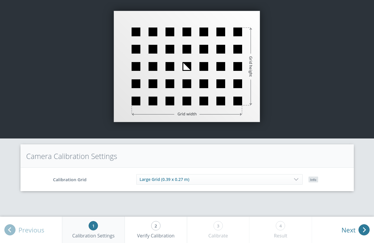
Fig. 46 Calibration settings
In the first step, the calibration grid must be specified. The Next button proceeds to the next step.
Verify calibration
In the next step, the current calibration can be verified. To perform the verification, the grid must be held such that it is simultaneously visible in both cameras. When the grid is detected, the calibration error is automatically computed and the result is displayed on the screen.
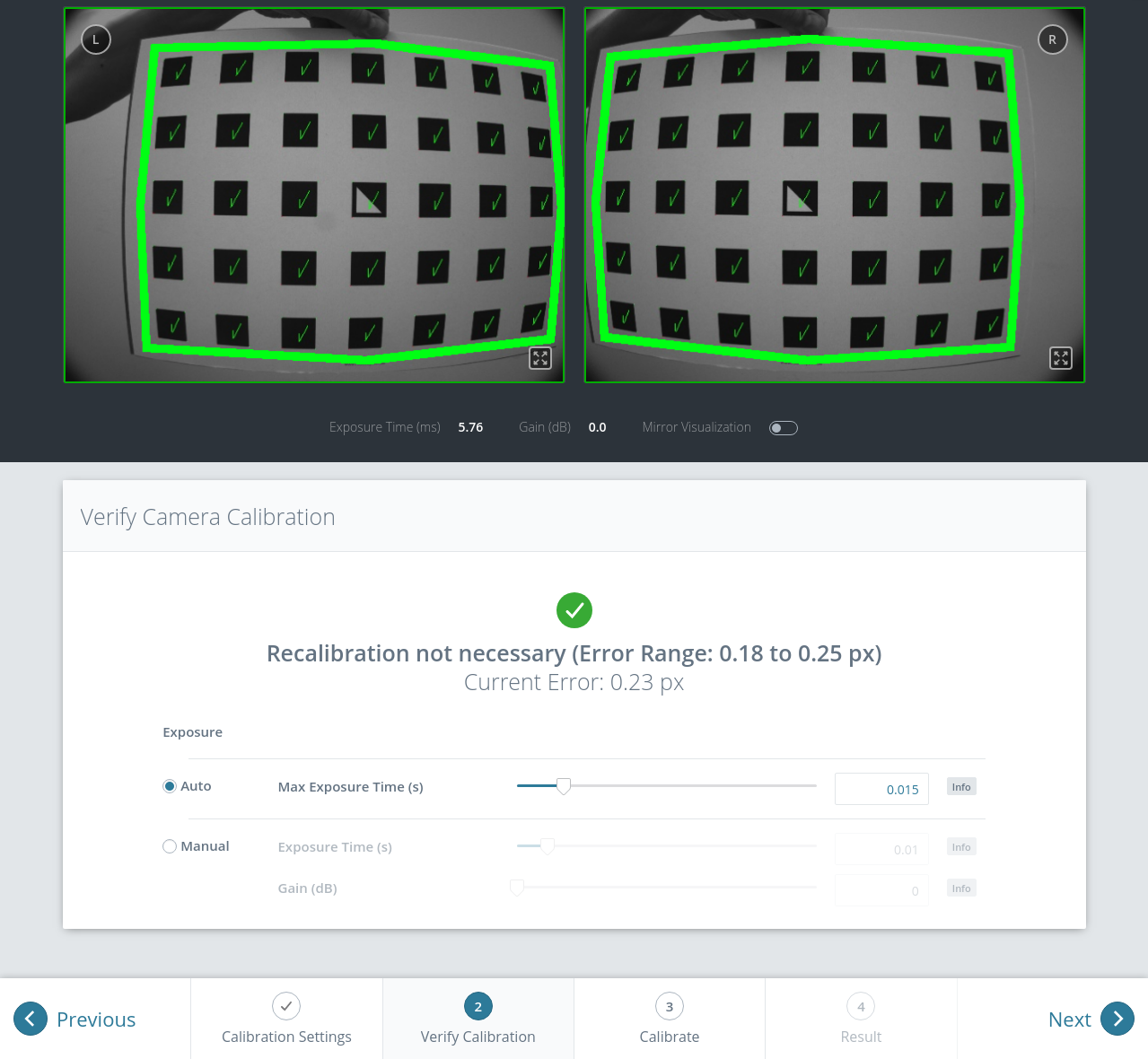
Fig. 47 Verification of calibration
Note
To compute a meaningful calibration error, the grid should be held as close as possible to the cameras. If the grid only covers a small section of the camera images, the calibration error will always be less than when the grid covers the full image. For this reason, the minimal and maximal calibration error during verification are shown in addition to the calibration error at the current grid position.
The typical calibration error is below 0.2 pixels. If the error is in this range, then the calibration procedure can be skipped. If the calibration error is greater, the calibration procedure should be performed to guarantee full sensor performance. The button Next starts the procedure.
Warning
A large error during verification can be due to miscalibrated cameras, an inaccurate calibration grid, or wrong grid width or height. In case you use a custom calibration grid, please make sure that the grid is accurate and the entered grid width and height are correct. Otherwise, manual calibration will actually decalibrate the cameras!
Calibrate
The camera’s exposure time should be set appropriately before starting the calibration. To achieve good calibration results, the images should be well-exposed and motion blur should be avoided. Thus, the maximum auto-exposure time should be as short as possible, but still allow a good exposure. The current exposure time is displayed below the camera images as shown in Fig. 49.
Full calibration consists of calibrating each camera individually (monocalibration) and then performing a stereo calibration to determine the relationship between them. In most cases, the intrinsic calibration of each camera does not get corrupted. For this reason, monocalibration is skipped by default during a recalibration, but can be performed by clicking Perform Monocalibration in the Calibrate tab. This should only be done if the result of the stereo calibration is not satisfactory.
Stereo calibration
During stereo calibration, both cameras are calibrated to each other to find their relative rotation and translation.
The camera images can also be displayed mirrored to simplify the correct positioning of the calibration grid.
First, the grid should be held as close as possible to the camera and very still. It must be fully visible in both images and the cameras should look perpendicularly onto the grid. If the grid is not perpendicular to the line of sight of the cameras, this will be indicated by small green arrows pointing to the expected positions of the grid corners (see Fig. 48).
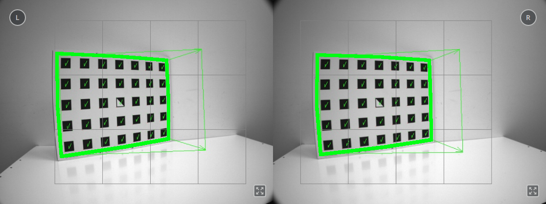
Fig. 48 Arrows indicating that the grid is not perpendicular to the camera’s line of sight during stereo calibration
The grid must be kept very still for detection. If motion blur occurs, the grid will not be detected. All grid cells that are drawn onto the image have to be covered by the calibration grid. This is visualized by filling the covered cells in green (see Fig. 49).
For the rc_visard all cells can be covered at once by holding the grid close enough.
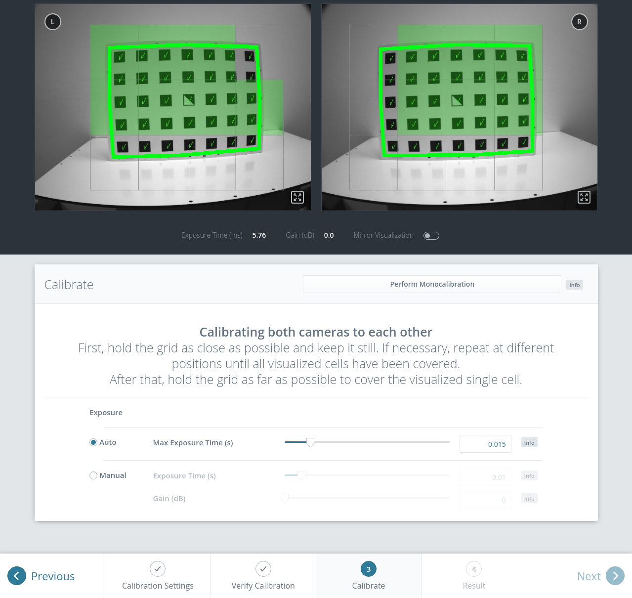
Fig. 49 Stereo calibration: Hold the grid as close as possible to fill all visualized cells
Note
If the check marks on the calibration grid all vanish, then either the camera does not look perpendicularly onto the grid, or the grid is too far away from the camera.
Once all grid cells are covered, they disappear and a single far cell is visualized. Now, the grid should be held as far as possible from the cameras, so that the small cell is covered. Arrows will indicate if the grid is still too close to the camera. When the grid is successfully detected at the far pose, the cell is filled in green and the result can be computed (see Fig. 50).
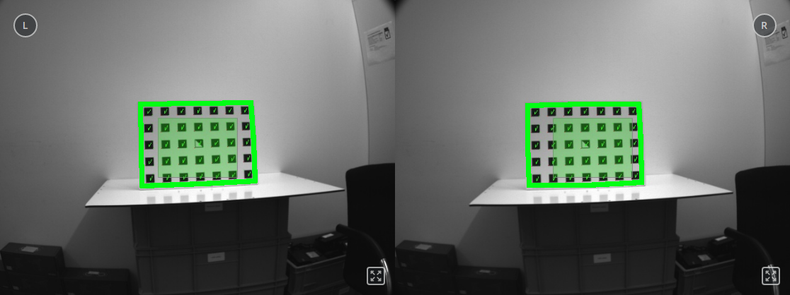
Fig. 50 Holding the grid far away during stereo calibration
If stereo calibration yields an unsatisfactory calibration error, then calibration should be repeated with monocalibration (see next Section Monocalibration).
Monocalibration
Monocalibration is the intrinsic calibration of each camera individually. Since the intrinsic calibration normally does not get corrupted, the monocalibration should only be performed if the result of stereo calibration is not satisfactory.
Click Perform Monocalibration in the Calibrate tab to start monocalibration.
For monocalibration, the grid has to be held in certain poses. The arrows from the grid corners to the green areas indicate that all grid corners should be placed inside the green areas. The green areas are called sensitive areas. The Size of Sensitive Area slider can control their size to ease calibration. However, please be aware that increasing their size too much may result in slightly lower calibration accuracy.
Holding the grid upside down is a common mistake made during calibration. Spotting this in this case is easy because the green lines from the grid corners into the green areas will cross each other as shown in Fig. 51.
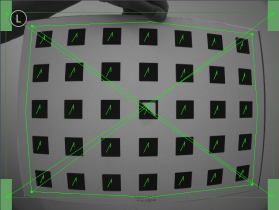
Fig. 51 Wrongly holding the grid upside down leads to crossed green lines.
Note
Calibration might appear cumbersome as it involves holding the grid in certain predefined poses. However, these poses are required to ensure an unbiased, high-quality calibration result.
The monocalibration process involves five poses for each camera as shown in Fig. 52.
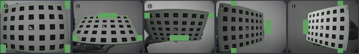
Fig. 52 Poses required for monocamera calibration
After the corners or sides of the grid are placed on top of the sensitive areas, the process automatically shows the next pose required. When the process is finished for the left camera, the same procedure is repeated for the right one.
Continue with the guidelines given in the previous Section Stereo calibration.
Storing the calibration result
Clicking the Compute Calibration button finishes the process and displays the final result. The indicated result is the mean reprojection error of all calibration points. It is given in pixels and typically has a value below 0.2.
Pressing Save Calibration applies the calibration and saves it to the device.
Note
The given result is the minimum error left after calibration. The real error is definitely not less than this, but could in theory be larger. This is true for every camera-calibration algorithm and the reason why we enforce holding the grid in very specific poses. Doing so ensures that the real calibration error cannot significantly exceed the reported error.
Warning
If a hand-eye calibration was stored on the rc_visard before camera calibration, the hand-eye calibration values could have become invalid. Please repeat the hand-eye calibration procedure.
Parameters
The module is called rc_stereocalib in the REST-API.
Note
The camera calibration module’s available parameters and status values are for internal use only and may change in the future without further notice. Calibration should only be performed through the Web GUI as described above.
Services
Note
The camera calibration module’s available service calls are for internal use only and may change in the future without further notice. Calibration should only be performed through the Web GUI as described above.