SilhouetteMatch
Introduction
The SilhouetteMatch component is an optional on-board component of the rc_visard, which detects objects by matching a predefined silhouette (“template”) to edges in an image.
Note
This component is optional and requires a separate SilhouetteMatch license to be purchased.
For the SilhouetteMatch component to work, special object templates are required for each type of object to be detected. Roboception offers a template generation service on their website, where the user can upload CAD files or recorded data of the objects and request object templates for the SilhouetteMatch component.
The object templates consist of significant edges of each object. These template edges are matched to the edges detected in the left and right camera images, considering the actual size of the objects and their distance from the camera. The poses of the detected objects are returned and can be used for grasping, for example.
Suitable objects
The SilhouetteMatch component is intended for objects which have significant edges on a common plane that is parallel to the base plane on which the objects are placed. This applies to flat, nontransparent objects, such as routed, laser-cut or water-cut 2D parts and flat-machined parts. More complex parts can also be detected if there are significant edges on a common plane, e.g. a special pattern printed on a flat surface.
The SilhouetteMatch component works best for objects on a texture-free base plane. The color of the base plane should be chosen such that a clear contrast between the objects and the base plane appears in the intensity image.
Suitable scene
The scene must meet the following conditions to be suitable for the SilhouetteMatch component:
- The objects to be detected must be suitable for the SilhouetteMatch component as described above.
- Only objects belonging to one specific template are visible at a time (unmixed scenario). In case other objects are visible as well, a proper region of interest (ROI) must be set.
- All visible objects are lying on a common base plane, which has to be calibrated.
- The offset between the base plane normal and the camera’s line of sight does not exceed 10 degrees.
- The objects are not partially or fully occluded.
- All visible objects are right side up (no flipped objects).
- The object edges to be matched are visible in both, left and right camera images.
Base-plane calibration
Before objects can be detected, a base-plane calibration must be performed. Thereby, the distance and angle of the plane on which the objects are placed is measured and stored persistently on the rc_visard.
Separating the detection of the base plane from the actual object detection renders scenarios possible in which the base plane is temporarily occluded. Moreover, it increases performance of the object detection for scenarios where the base plane is fixed for a certain time; thus, it is not necessary to continuously re-detect the base plane.
The base-plane calibration can be performed in three different ways, which will be explained in more detail further down:
- AprilTag based
- Stereo based
- Manual
The base-plane calibration is successful if the normal vector of the estimated base plane is at most 10 degrees offset to the camera’s line of sight. If the base-plane calibration is successful, it will be stored persistently on the rc_visard until it is removed or a new base-plane calibration is performed.
Note
To avoid privacy issues, the image of the persistently stored base-plane calibration will appear blurred after rebooting the rc_visard.
In scenarios where the base plane is not accessible for calibration, a plane parallel to the base-plane can be calibrated.
Then an offset parameter can be used to shift the estimated plane onto the actual base plane where
the objects are placed. The offset parameter gives the distance in meters by which the estimated plane
is shifted towards the camera.
In the REST-API, a plane is defined by a normal and a distance.
normal is a normalized 3-vector, specifying the normal of the plane.
The normal points away from the camera.
distance represents the distance of the plane from the camera along the normal.
Normal and distance can also be interpreted as \(a\), \(b\), \(c\), and \(d\) components
of the plane equation, respectively:
AprilTag based base-plane calibration
AprilTag detection (ref. TagDetect) is used to find AprilTags in the scene and fit a plane through them. At least three AprilTags must be placed on the base plane so that they are visible in the left and right camera images. The tags should be placed such that they are spanning a triangle that is as large as possible. The larger the triangle, the more accurate is the resulting base-plane estimate. Use this method if the base plane is untextured and no external random dot projector is available. This calibration mode is available via the REST-API interface and the rc_visard Web GUI.
Stereo based base-plane calibration
The 3D point cloud computed by the stereo matching component is used to fit a plane
through its 3D points.
Therefore, the region of interest (ROI) for this method must
be set such that only the relevant base plane is included.
The plane_preference parameter allows to select whether the plane closest to
or farthest from the camera should be used as base plane.
Selecting the closest plane can be used in scenarios where the base plane is
completely occluded by objects or not accessible for calibration.
Use this method if the base plane is well textured or you can
make use of a random dot projector to project texture on the base plane.
This calibration mode is available via the REST-API interface
and the rc_visard Web GUI.
Manual base-plane calibration
The base plane can be set manually if its parameters are known, e.g. from previous calibrations. This calibration mode is only available via the REST-API interface and not the rc_visard Web GUI.
Setting a region of interest
If objects are to be detected only in part of the camera’s field of view, a region of interest (ROI) can be set accordingly. This ROI is defined as a rectangular part of the left camera image, and can be set via the REST-API interface or the rc_visard Web GUI. The Web GUI offers an easy-to-use selection tool. Up to 50 ROIs can be set and stored persistently on the rc_visard. Each ROI must have a unique name to address a specific ROI in the base-plane calibration or object detection process.
In the REST-API, a 2D ROI is defined by the following values:
id: Unique name of the region of interestoffset_x,offset_y: offset in pixels along the x-axis and y-axis from the top-left corner of the image, respectivelywidth,height: width and height in pixels
Detection of objects
Objects can only be detected after a successful base-plane calibration. It must be ensured that the position and orientation of the base plane does not change before the detection of objects. Otherwise, the base-plane calibration must be renewed.
For triggering the object detection, in general, the following information must be provided to the SilhouetteMatch component:
- The template of the object to be detected in the scene.
- The coordinate frame in which the poses of the detected objects shall be returned (ref. Hand-eye calibration).
Optionally, further information can be given to the SilhouetteMatch component:
- An offset in case the objects are lying not on the base plane but on a plane parallel to it. The offset is the distance between both planes given in the direction towards the camera. If omitted, an offset of 0 is assumed.
- The region of interest in which the objects should be detected. If omitted, objects are matched in the whole image.
- The current robot pose in case the chosen coordinate frame for the poses is
externaland the camera is mounted on the robot.
On the Web GUI the detection can be tested in the “Try Out” section of the SilhouetteMatch component’s tab. The result is visualized as shown in Fig. 57.
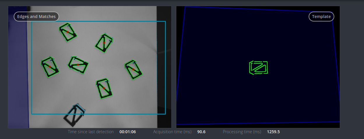
Fig. 57 Result image of the SilhouetteMatch component as shown in the Web GUI
The right image shows the calibrated base plane in blue and the template to be matched in green. The template is warped to the size and tilt matching objects on the calibrated base plane would have.
The left image shows the detection result. The shaded blue area on the left is the region of the left camera image which does not overlap with the right image, and in which no objects can be detected. The chosen region of interest is shown as bold petrol rectangle. The detected edges in the image are shown in light blue and the matches with the template are shown in green. The red circles are the origins of the detected objects as defined in the template. The poses of the object origins in the chosen coordinate frame are returned as results. In case the objects are rotationally symmetric, all returned poses will have the same orientation. For rotationally non-symmetric objects, the orientation of the detected objects is aligned with the normal of the base plane.
The detection results and runtimes are affected by several run-time parameters which are listed and explained further down. Improper parameters can lead to time-outs of the SilhouetteMatch component’s detection process.
Interaction with other components
Internally, the SilhouetteMatch component depends on, and interacts with other on-board components as listed below.
Note
All changes and configuration updates to these components will affect the performance of the SilhouetteMatch component.
Stereo camera and stereo matching
The SilhouetteMatch component makes internally use of the rectified images from the
Stereo camera component (rc_stereocamera).
Thus, the exposure time should be set properly to achieve the optimal performance of the component.
For base-plane calibration in stereo mode the disparity images from the Stereo matching component
(rc_stereomatching) are used. Apart from that,
the stereo-matching component should not be run in parallel to the SilhouetteMatch component, because the detection runtime increases.
For best results it is recommended to enable smoothing for Stereo matching.
IO and Projector Control
In case the rc_visard is used in conjunction with an external random dot projector and
the IO and Projector Control component (rc_iocontrol),
the projector should be used for the stereo-based base-plane calibration.
The projected pattern must not be visible in the left and right camera images during object detection
as it interferes with the matching process.
Therefore, it must either be switched off or operated in ExposureAlternateActive mode.
Hand-eye calibration
In case the camera has been calibrated to a robot, the SilhouetteMatch component can automatically provide
poses in the robot coordinate frame.
For the SilhouetteMatch node’s Services, the frame of the
input and output poses and plane coordinates can be controlled with the pose_frame
argument.
Two different pose_frame values can be chosen:
- Camera frame (
camera). All poses and plane coordinates provided to and by the component are in the camera frame. - External frame (
external). All poses and plane coordinates provided to and by the component are in the external frame, configured by the user during the hand-eye calibration process. The component relies on the on-board Hand-eye calibration component to retrieve the camera mounting (static or robot mounted) and the hand-eye transformation. If the sensor mounting is static, no further information is needed. If the sensor is robot-mounted, therobot_poseis required to transform poses to and from theexternalframe.
All pose_frame values that are not camera or external are rejected.
Note
If no hand-eye calibration is available, all pose_frame values should be set to camera.
Note
If the hand-eye calibration has changed after base-plane calibration, the base-plane calibration will be marked as invalid and must be renewed.
If the sensor is robot-mounted, the current robot_pose has to be provided depending on the value of pose_frame:
- If
pose_frameis set toexternal, providing the robot pose is obligatory. - If
pose_frameis set tocamera, providing the robot pose is optional.
If the current robot pose is provided during calibration, it is stored persistently on the rc_visard.
If the updated robot pose is later provided during get_base_plane_calibration or detect_object
as well, the base-plane calibration will be transformed automatically to this new robot pose.
This enables the user to change the robot pose (and thus camera position)
between base-plane calibration and object detection.
Note
Object detection can only be performed if the limit of 10 degrees angle offset between the base plane normal and the camera’s line of sight is not exceeded.
Parameters
The SilhouetteMatch software component is called rc_silhouettematch in the REST-API and is represented by the
SilhouetteMatch page in the Modules tab of the
Web GUI.
The user can explore and configure the rc_silhouettematch
component’s run-time parameters, e.g. for development and testing, using the Web GUI or the
REST-API interface.
Parameter overview
This component offers the following run-time parameters:
| Name | Type | Min | Max | Default | Description |
|---|---|---|---|---|---|
edge_sensitivity |
float64 | 0.1 | 1.0 | 0.6 | sensitivity of the edge detector |
match_max_distance |
float64 | 0.0 | 10.0 | 2.5 | maximum allowed distance in pixels between the template and the detected edges in the image |
match_percentile |
float64 | 0.7 | 1.0 | 0.85 | percentage of template pixels that must be within the maximum distance to successfully match the template |
max_number_of_detected_objects |
int32 | 1 | 20 | 10 | maximum number of detected objects |
quality |
string | - | - | High | High, Medium, or Low |
Description of run-time parameters
Each run-time parameter is represented by a row on the Web GUI’s SilhouetteMatch Module tab. The name in the Web GUI is given in brackets behind the parameter name and the parameters are listed in the order they appear in the Web GUI:
quality(Quality)- Object detection can be performed on images with different resolutions:
High(1280 x 960),Medium(640 x 480) andLow(320 x 240). The lower the resolution, the lower the detection time, but the fewer details of the objects are visible. max_number_of_detected_objects(Maximum Object Number)- This parameter gives the maximum number of objects to detect in the scene. If more than the given number of objects can be detected in the scene, only the objects with the highest matching results are returned.
match_max_distance(Maximum Matching Distance)- This parameter gives the maximum allowed pixel distance of an image edge pixel from the object edge pixel in the template to be still considered as matching. If the object is not perfectly represented in the template, it might not be detected when this parameter is low. High values, however, might lead to false detections in case of a cluttered scene or the presence of similar objects, and also increase runtime.
match_percentile(Matching Percentile)- This parameter indicates how strict the matching process should be. The matching percentile is the ratio of template pixels that must be within the Maximum Matching Distance to successfully match the template. The higher this number, the more accurate the match must be to be considered as valid.
edge_sensitivity(Edge Sensitivity)- This parameter influences how many edges are detected in the camera images. The higher this number, the more edges are found in the intensity image. That means, for lower numbers, only the most significant edges are considered for template matching. A large number of edges in the image might increase the detection time.
Status values
This component reports the following status values:
| Name | Description |
|---|---|
calibrate_service_time |
Processing time of the base-plane calibration, including data acquisition time |
data_acquisition_time |
Time in seconds required by the last active service to acquire images |
detect_service_time |
Processing time of the object dection, including data acquisition time |
last_timestamp_processed |
The timestamp of the last processed dataset |
Services
The user can explore and call the rc_silhouettematch component’s services,
e.g. for development and testing, using the
REST-API interface or
the rc_visard
Web GUI.
Each service response contains a return_code,
which consists of a value plus an optional message.
A successful service returns with a return_code value of 0.
Negative return_code values indicate that the service failed.
Positive return_code values indicate that the service succeeded with additional information.
| Code | Description |
|---|---|
| 0 | Success |
| -1 | An invalid argument was provided |
| -3 | An internal timeout occurred, e.g. during object detection |
| -4 | Data acquisition took longer than the maximum allowed time of 5.0 seconds |
| -7 | Data could not be read or written to persistent storage |
| -10 | New element could not be added as the maximum storage capacity of regions of interest or templates has been exceeded |
| -100 | An internal error occurred |
| -101 | Detection of the base plane failed |
| -102 | The hand-eye calibration changed since the last base-plane calibration |
| -104 | Offset between the base plane normal and the camera’s line of sight exceeds 10 degrees |
| 10 | The maximum storage capacity of regions of interest or templates has been reached |
| 101 | An existing region of interest was overwritten |
| 102 | The provided robot pose was ignored |
| 103 | The base plane was not transformed to the current camera pose, e.g. because no robot pose was provided during base-plane calibration |
The SilhouetteMatch component offers the following services.
calibrate_base_plane
Triggers the calibration of the base plane, as described in Base-plane calibration. A successful base-plane calibration is stored persistently on the rc_visard and returned by this service. The base-plane calibration is persistent over firmware updates and rollbacks.
All images used by the service are guaranteed to be newer than the service trigger time.
Request:
The definition for the request arguments with corresponding datatypes is:
{
  "offset": "float64",
  "plane": {
    "distance": "float64",
    "normal": {
      "x": "float64",
      "y": "float64",
      "z": "float64"
    }
  },
  "plane_estimation_method": "string",
  "pose_frame": "string",
  "region_of_interest_2d_id": "string",
  "robot_pose": {
    "orientation": {
      "w": "float64",
      "x": "float64",
      "y": "float64",
      "z": "float64"
    },
    "position": {
      "x": "float64",
      "y": "float64",
      "z": "float64"
    }
  },
  "stereo": {
    "plane_preference": "string"
  }
}
Required arguments:
plane_estimation_method: method to use for base-plane calibration. Valid values areSTEREO,APRILTAG,MANUAL.
pose_frame: see Hand-eye calibration.Potentially required arguments:
planeifplane_estimation_methodisMANUAL: plane that will be set as base-plane calibration.
robot_pose: see Hand-eye calibration.
region_of_interest_2d_id: ID of the region of interest for base-plane calibration.Optional arguments:
offset: offset in meters by which the estimated plane will be shifted towards the camera.
plane_preferenceinstereo: whether the plane closest to or farthest from the camera should be used as base plane. This option can be set only ifplane_estimation_methodisSTEREO. Valid values areCLOSESTandFARTHEST. If not set, the default isFARTHEST.Response:
The definition for the response with corresponding datatypes is:
{
  "plane": {
    "distance": "float64",
    "normal": {
      "x": "float64",
      "y": "float64",
      "z": "float64"
    },
    "pose_frame": "string"
  },
  "return_code": {
    "message": "string",
    "value": "int16"
  },
  "timestamp": {
    "nsec": "int32",
    "sec": "int32"
  }
}
plane: calibrated base plane.
timestamp: timestamp of the image set the calibration ran on.
return_code: holds possible warnings or error codes and messages.
get_base_plane_calibration
Returns the configured base-plane calibration.
Request:
The definition for the request arguments with corresponding datatypes is:
{
  "pose_frame": "string",
  "robot_pose": {
    "orientation": {
      "w": "float64",
      "x": "float64",
      "y": "float64",
      "z": "float64"
    },
    "position": {
      "x": "float64",
      "y": "float64",
      "z": "float64"
    }
  }
}
Required arguments:
pose_frame: see Hand-eye calibration.Potentially required arguments:
robot_pose: see Hand-eye calibration.Response:
The definition for the response with corresponding datatypes is:
{
  "plane": {
    "distance": "float64",
    "normal": {
      "x": "float64",
      "y": "float64",
      "z": "float64"
    },
    "pose_frame": "string"
  },
  "return_code": {
    "message": "string",
    "value": "int16"
  }
}
delete_base_plane_calibration
Deletes the configured base-plane calibration.
This service has no arguments.
The definition for the response with corresponding datatypes is:
{
  "return_code": {
    "message": "string",
    "value": "int16"
  }
}
set_region_of_interest_2d
Persistently stores a 2D region of interest on the rc_visard. All configured 2D regions of interest are persistent over firmware updates and rollbacks.
The definition for the request arguments with corresponding datatypes is:
{
  "region_of_interest_2d": {
    "height": "uint32",
    "id": "string",
    "offset_x": "uint32",
    "offset_y": "uint32",
    "width": "uint32"
  }
}
region_of_interest_2d: see Setting a region of interest.The definition for the response with corresponding datatypes is:
{
  "return_code": {
    "message": "string",
    "value": "int16"
  }
}
get_regions_of_interest_2d
Returns the configured 2D regions of interest with the requested
region_of_interest_2d_ids. If noregion_of_interest_2d_idsare provided, all configured 2D regions of interest are returned.The definition for the request arguments with corresponding datatypes is:
{
  "region_of_interest_2d_ids": [
    "string"
  ]
}
The definition for the response with corresponding datatypes is:
{
  "regions_of_interest": [
    {
      "height": "uint32",
      "id": "string",
      "offset_x": "uint32",
      "offset_y": "uint32",
      "width": "uint32"
    }
  ],
  "return_code": {
    "message": "string",
    "value": "int16"
  }
}
delete_regions_of_interest_2d
Deletes the configured 2D regions of interest with the requested
region_of_interest_2d_ids. All 2D regions of interest to be deleted must be explicitly specified inregion_of_interest_2d_ids.The definition for the request arguments with corresponding datatypes is:
{
  "region_of_interest_2d_ids": [
    "string"
  ]
}
The definition for the response with corresponding datatypes is:
{
  "return_code": {
    "message": "string",
    "value": "int16"
  }
}
detect_object
Triggers an object detection as described in Detection of objects and returns the pose of all found object instances. The maximum number of returned instances can be controlled with the
max_number_of_detected_objectsparameter.All images used by the service are guaranteed to be newer than the service trigger time.
Request:
The definition for the request arguments with corresponding datatypes is:
{
  "object_to_detect": {
    "object_id": "string",
    "region_of_interest_2d_id": "string"
  },
  "offset": "float64",
  "pose_frame": "string",
  "robot_pose": {
    "orientation": {
      "w": "float64",
      "x": "float64",
      "y": "float64",
      "z": "float64"
    },
    "position": {
      "x": "float64",
      "y": "float64",
      "z": "float64"
    }
  }
}
Required arguments:
object_idinobject_to_detect: ID of the template which should be detected.
pose_frame: see Hand-eye calibration.Potentially required arguments:
robot_pose: see Hand-eye calibration.Optional arguments:
offset: offset in meters by which the base-plane calibration will be shifted towards the camera.Response:
The definition for the response with corresponding datatypes is:
{
  "instances": [
    {
      "id": "string",
      "object_id": "string",
      "pose": {
        "orientation": {
          "w": "float64",
          "x": "float64",
          "y": "float64",
          "z": "float64"
        },
        "position": {
          "x": "float64",
          "y": "float64",
          "z": "float64"
        }
      },
      "pose_frame": "string",
      "timestamp": {
        "nsec": "int32",
        "sec": "int32"
      }
    }
  ],
  "object_id": "string",
  "return_code": {
    "message": "string",
    "value": "int16"
  },
  "timestamp": {
    "nsec": "int32",
    "sec": "int32"
  }
}
object_id: ID of the detected template.
instances: list of detected object instances.
timestamp: timestamp of the image set the detection ran on.
return_code: holds possible warnings or error codes and messages.
save_parameters
This service saves the currently set parameters persistently. Thereby, the same parameters will still apply after a reboot of the rc_visard. The node parameters are not persistent over firmware updates and rollbacks.
This service has no arguments.
The definition for the response with corresponding datatypes is:
{
  "return_code": {
    "message": "string",
    "value": "int16"
  }
}
reset_defaults
This service resets all parameters of the component to its default values, as listed in above table. The reset does not apply to regions of interest and base-plane calibration.
This service has no arguments.
The definition for the response with corresponding datatypes is:
{
  "return_code": {
    "message": "string",
    "value": "int16"
  }
}
Template Upload
For template upload, download and listing, special REST-API endpoints are provided. Up to 50 templates can be stored persistently on the rc_visard.
-
GET/nodes/rc_silhouettematch/templates¶ Get list of all rc_silhouettematch templates.
Template request
GET /api/v1/nodes/rc_silhouettematch/templates HTTP/1.1
Template response
HTTP/1.1 200 OK
Content-Type: application/json

[
  {
    "id": "string"
  }
]
Response Headers: - Content-Type – application/json
Status Codes: - 200 OK – successful operation (returns array of Template)
- 404 Not Found – node not found
Referenced Data Models:
-
GET/nodes/rc_silhouettematch/templates/{id}¶ Get a rc_silhouettematch template. If the requested content-type is application/octet-stream, the template is returned as file.
Template request
GET /api/v1/nodes/rc_silhouettematch/templates/<id> HTTP/1.1
Template response
HTTP/1.1 200 OK
Content-Type: application/json

{
  "id": "string"
}
Parameters: - id (string) – id of the template (required)
Response Headers: - Content-Type – application/json application/octet-stream
Status Codes: - 200 OK – successful operation (returns Template)
- 404 Not Found – node or template not found
Referenced Data Models:
-
PUT/nodes/rc_silhouettematch/templates/{id}¶ Create or update a rc_silhouettematch template.
Template request
PUT /api/v1/nodes/rc_silhouettematch/templates/<id> HTTP/1.1
Accept: multipart/form-data application/json
Template response
HTTP/1.1 200 OK
Content-Type: application/json

{
  "id": "string"
}
Parameters: - id (string) – id of the template (required)
Form Parameters: - file – template file (required)
Request Headers: - Accept – multipart/form-data application/json
Response Headers: - Content-Type – application/json
Status Codes: - 200 OK – successful operation (returns Template)
- 400 Bad Request – Template is not valid or max number of templates reached
- 403 Forbidden – forbidden, e.g. because there is no valid license for this component.
- 404 Not Found – node or template not found
- 413 Request Entity Too Large – Template too large
Referenced Data Models:
-
DELETE/nodes/rc_silhouettematch/templates/{id}¶ Remove a rc_silhouettematch template.
Template request
DELETE /api/v1/nodes/rc_silhouettematch/templates/<id> HTTP/1.1
Accept: application/json
Parameters: - id (string) – id of the template (required)
Request Headers: - Accept – application/json
Response Headers: - Content-Type – application/json
Status Codes: - 200 OK – successful operation
- 403 Forbidden – forbidden, e.g. because there is no valid license for this component.
- 404 Not Found – node or template not found